

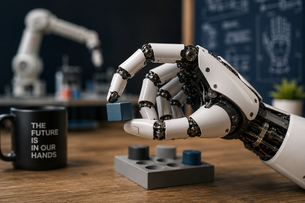
An industrial robot arm gets most of the attention. It is tall, fast, articulate, and easy to recognize in a factory video. Yet the arm rarely touches the product by itself. A smaller assembly at its wrist performs that job. This “hand,” usually called an end-of-arm tool, can decide whether a part is lifted cleanly, held without damage, presented accurately, and released into the correct place.
For a team considering a system integrator Singapore project, that distinction changes the first design conversation. The useful opening question is not simply which robot brand or payload class to buy. It is how a real component will arrive, where it may vary, which surfaces may be touched, and what evidence will confirm that every pick and release happened as intended.

Robot Arms Only Solve the Motion Problem
A robot arm creates a repeatable path through space. Its controller can send the wrist to taught positions, coordinate speed, and synchronize movement with surrounding equipment. Those capabilities matter, but they describe the journey rather than the contact event. If a part reaches the pick point rotated, nested beneath another part, or slightly outside the expected height, a perfect path can still produce a failed pick.
A Fast Arm Can Still Mishandle Parts
Imagine a small plastic tube arriving from a feeder. The arm may reach the same coordinates on every cycle, while the tube itself changes orientation by a few degrees. A vacuum cup might land across an edge and leak. Mechanical fingers might squeeze an unsupported wall. The motion program has repeated correctly, but the physical assumptions beneath it have not.
Headline arm speed says little about a complete handling result. The rest of the cell still needs a stable presentation point, a tool shaped for the available contact surfaces, and a way to detect whether the component is actually under control. Each element removes a different source of uncertainty. Leave one out of the design discussion, and the unanswered question usually returns during commissioning or production.
The Gripper Defines the Product Contact
End-of-arm tooling can be simple or highly specialized. Vacuum cups use pressure difference to hold a surface. Parallel fingers close around an edge or feature. Soft tooling spreads force over a delicate area. A custom nest may support a component while a second action turns, inserts, or inspects it. The correct choice depends on the part, not on which option looks most sophisticated.
Vacuum Tools Need a Stable Seal Surface
Vacuum handling is attractive because it can lift a part without clamping two sides. It still needs a surface large and smooth enough to form a reliable seal. Texture, holes, curvature, dust, and flexible walls can change the result. A sensible design therefore considers cup geometry, vacuum level, recovery after a missed seal, and sensing that distinguishes a confirmed grip from an empty move.
The medical-device examples described by Motionwell Automation include Epson SCARA pick-and-place with vacuum end-of-arm tooling for delicate component sorting. That combination is useful as a system example: the robot supplies controlled movement, while the vacuum tool and its supporting logic manage the actual product contact. Neither element completes the task alone.
Mechanical Fingers Need Controlled Contact Force
Finger grippers avoid the need for an airtight surface, but they introduce other decisions. The finger profile must locate the part without scraping a critical area. Closing force must be high enough to resist motion and low enough to avoid deformation. The designer must also consider what happens when two parts arrive together or when a finger closes against an empty fixture.
The custom tool may be less photogenic than the arm, but it is far more specific to the application. That specificity makes it hard to replace with a catalog choice made from payload alone. Motionwell Automation lists custom end-of-arm tooling within its robotics integration work, reflecting a practical reality: the wrist interface is where a general-purpose machine becomes a product-handling system.
Feeders and Fixtures Shape Every Successful Pick
The robot hand cannot correct unlimited disorder. Feeders separate bulk parts and guide them toward a known orientation. Fixtures establish a repeatable location and support surfaces that might flex during contact. Together, they reduce the number of conditions the gripper must tolerate. A robust cell is therefore not just a robot with a clever hand; it is a chain that prepares, locates, grips, verifies, and releases the part.
Orientation Errors Start Before the Robot Moves
A feeder track that occasionally presents a tube backward creates a different problem from a gripper that loses vacuum during travel. The symptoms may look similar because both can end with a missing part at the destination. Their remedies are different. One may require mechanical guidance or a vision check before pickup. The other may require a different cup, pressure threshold, travel profile, or recovery routine.
Motionwell Automation describes vibratory feeders, starwheel mechanisms, and handling for parts such as vials, syringes, and tubes. Those examples show why part presentation belongs in the same design discussion as the robot. When the incoming state is controlled, the tool can be simpler. When it is not, the cell needs sensing and an explicit route for components that do not meet the expected condition.
Cleanroom Materials Change the Tooling Choice
Medical production can add another boundary: materials and surfaces may need to suit a controlled environment. A tool that grips well but sheds particles, traps residue, or cannot be cleaned appropriately is not a complete answer. Motionwell Automation notes nylon and POM among its jig and fixture materials, as well as cleanroom-compatible automation. Those facts do not select a material for every project, but they show that environmental requirements should reach the tooling specification rather than remain a general note.
The same principle applies to change parts and wear items. A production team should know which surfaces contact the product, how those items are inspected, and what must be rechecked after replacement. This is less about adding documentation for its own sake than preserving the geometry and force conditions on which the handling method depends.
Map the Contact Interface Before Buying Hardware
A compact interface map helps a buyer turn an impressive demonstration into a set of observable questions. It does not need to predict every fault. It only needs to connect each physical element to the assumption it controls and to a result that can be seen during a representative cycle.
| Contact interface | Question to answer | Observable acceptance signal |
| Feeder | Which orientations can reach the pick point? | Incorrect presentations are blocked or routed away |
| Fixture | Which surfaces locate and support the part? | The part remains stable during contact |
| Gripper or vacuum tool | Where and how is holding force applied? | The part travels without slip or damage |
| Grip sensor | How is a successful pickup confirmed? | An empty or partial grip stops the normal sequence |
| Release point | How is separation from the tool verified? | The part is present at the destination and absent from the tool |
This table also exposes mismatched assumptions early. If the feeder can deliver several orientations but the tool tolerates only one, the gap is visible. If the tool can hold a part but the controller has no grip confirmation, a successful move cannot be distinguished from an empty one until later. The discussion stays tied to the physical event rather than drifting into a list of attractive hardware features.

Specify the Hand Before Comparing Robot Brands
Bring Real Parts and Failure Samples
Representative parts are more useful than ideal drawings alone. They reveal surface variation, flexible areas, gate marks, dimensional spread, and packaging effects that influence gripping. Known problem samples are valuable for the same reason. A tooling concept should encounter the bent flange, shallow seal surface, or reversed presentation before its geometry becomes expensive to change.
Buyers can then ask for a handling demonstration built around the difficult cases, not only the cleanest component. The goal is not to demand that one tool absorb every imaginable variation. It is to establish which variations are accepted, which are rejected before pickup, and which trigger a controlled stop. Clear boundaries make the design easier to review and the eventual exceptions easier to diagnose.
Write Acceptance Around Grip and Release
Acceptance language should follow the product through the contact sequence. The part arrives in an allowed orientation. The tool establishes contact. Grip confirmation becomes true before travel. The component remains supported through the motion. Release is confirmed at the destination. An unsuccessful step produces a defined response without sending an uncertain part forward.
Once those events are explicit, comparing arms becomes more meaningful. Reach, payload, cycle time, controller features, and service considerations still matter, but they are evaluated inside a defined task. The smaller tool at the wrist is no longer an accessory added after the main decision. It is the mechanism that translates general robotic motion into careful product handling.
Before approving an arm, finish the smaller drawing at its wrist. Define the incoming part, the allowed touch surfaces, the holding method, the proof of grip, and the proof of release. Then the arm can be chosen for a job that is already understood instead of being asked to rescue an undefined one.

Sandra Larson is a writer with the personal blog at ElizabethanAuthor and an academic coach for students. Her main sphere of professional interest is the connection between AI and modern study techniques. Sandra believes that digital tools are a way to a better future in the education system.