
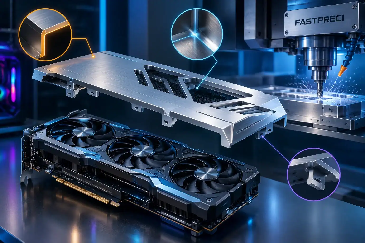
A graphics card is often the visual centerpiece of a PC build, so it’s no surprise that enthusiasts want to replace the stock shroud and backplate with something of their own. A machined aluminum cover can look excellent, but the design that looks good in CAD is not always the one that machines well. A few decisions made before any metal is cut will determine whether you get a clean prototype or an expensive lesson.
Start with How the Part Attaches
A GPU cover has to do more than look good. It clips onto or bolts to the card, clears the fans and heatsink, and has to stay put. Before refining the styling, pin down:
- Mounting points and clearances. Measure the actual card or use an accurate 3D model. Small errors in screw positions or cooler height become fit problems.
- Airflow. Covers that block intake or exhaust paths can hurt cooling, so keep vents and fan openings in mind from the start.
- Which features are functional. Clips, grooves, and retention features can’t simply be deleted to make machining easier, so know which ones are essential.
Material and Finish
6061 aluminum is a common choice for parts like this. It machines well, it’s light, and it takes a brushed finish nicely. The finish deserves as much thought as the material:
- A brushed surface is forgiving of minor machining marks but shows handling damage, so visible faces need protection throughout production.
- Engraved or recessed graphics should be planned alongside the finish. Recessed text filled with black paint contrasts well against brushed metal, and recessed geometry is often easier to execute cleanly than raised text.
- Decide early which surfaces are appearance-critical and which are hidden. This lets the machinist focus effort where it shows.
Watch the Thin Walls
Covers are mostly shell: large areas of material removed, leaving thin walls behind. That is where problems tend to appear. Thin sections can flex under cutting forces, vibrate, or spring out of shape once the part is released from the fixture.
A well-documented example is a custom aluminum GPU cover project for a French PC modder. The original design had 2 mm walls in areas needing heavy material removal. Rather than thicken the whole cover, the team increased those walls to 5 mm only where machining risk was highest, which kept the intended look intact. The takeaway is that local adjustments often solve the problem without changing the design’s character.
Be Selective About Undercuts
Undercuts are features where material overhangs the cutter’s path, and they limit tool access. They often require special cutters or staged operations, which adds cost and risk. Many can be replaced with a simple vertical wall without anyone noticing.
The key is to ask what each undercut is for. In that same project, the engineers initially proposed removing undercuts, and then learned that some were what held the backplate onto the card. After reviewing a 3D assembly model together, they removed the unnecessary ones and kept the functional ones. Removing a feature you don’t understand can break the part just as surely as keeping one that can’t be machined.
Pay Attention to Wall Transitions
Sharp internal corners and abrupt changes in wall thickness concentrate stress and are harder to machine cleanly. Adding fillets at wall roots (the project above used R3) and favoring vertical walls where possible makes the part both stronger and easier to cut. These are small CAD changes that cost nothing and pay off during machining.
Choose the Process That Fits the Part
For a one-off or small run, custom CNC milling is usually the sensible route. It needs no tooling, handles complex 3D geometry, and lets you iterate between prototypes. Casting or extrusion only start to make economic sense at volumes most hobby projects never reach.
When you pick a shop, ask whether they’ll review your design before quoting. A good manufacturing review catches issues like thin walls, inaccessible features, and conflicting finish requirements while changes are still cheap.
Tolerances and Surface Roughness
Don’t over-specify. A cosmetic cover rarely needs tight tolerances everywhere. General tolerances in the ISO 2768-m range and a surface roughness around Ra 3.2 µm were enough for the project above. Reserve tighter tolerances for mounting features and interfaces with the card itself. Every unnecessary tight tolerance adds inspection time and cost.
A Pre-Machining Checklist
Before you send files to a shop, confirm that you have:
- An accurate model of the card, including mounting points and cooler dimensions.
- A clear list of functional features, such as clips and undercuts, that must stay.
- Wall thicknesses checked, with thin areas flagged and thickened where needed.
- Fillets at internal corners and wall roots.
- Engraving depth and style (raised or recessed) matched to the intended finish.
- Material, finish, and general tolerances specified, with tight ones reserved for fit-critical features.
- A plan to test-fit the prototype before committing to anything more.
Final Thoughts
A custom GPU cover is a small part with a lot of competing demands: looks, fit, cooling, and manufacturability. Much like putting together the rest of a gaming setup, the best results come from treating machining as part of the design process rather than an afterthought. Understand why each feature exists, simplify what you can, protect what you must, and have someone with machining experience look at the design before the first cut.