

So when I last left you, we had a working Arcade 1UP Pac-Man cabinet and a selection of additional parts purchased to allow it to play more than just Pac-Man and Pac-Man Plus. Let’s open up this pickle jar.
The first thing that needed to be done is to remove the original control panel. If you have done any research into upgrading these types of cabinets, most have been done to the Street Fighter Edition cabinet. The reason for that is the control panel for it is already a two player panel. No need to recreate the wheel. All that was required for it was two add two buttons as RetroPie, the most popular gaming emulator software for Raspberry Pi requires a select button for each player. In the Pac-Man Control panel’s case, it is a one player board. So rather than try to adapt it to a two player board, I left it intact and will just create a new two player control panel, using the original as a template for size. Just to remind you, this is the original control panel.
Nothing too fancy, is it? The plus side to this, if I ever want to put it back to its original state, it is a quick change back. The control panel is held in by four screws and a connecting ribbon. With it removed, now we can open up the back of the cabinet.
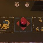
The fortunate thing here is there is ample room to store the additional parts being added. First things first, I needed to access the monitor connections. These are being covered by the box that contains the game roms and the control panel interface. Remove a few screws and it can be unplugged from the monitor. This is what that circuit board looks like:
I will save this board in the chance I need to go back to factory standard. The wide ribbon shown is what attaches to the control panel. So now that the control panel and the system board is removed, I now need to install the new monitor interface.
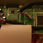
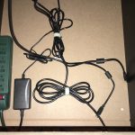
This is so easy that even I can do it. The Monitor has two plugs that attached it to the original board. The new LCD control board has a place for those two plugs. In addition, there is a ground wire with a metal grommet that a screw can go through. You will have to supply a small screw with a nut to attach this ground wire. Again, I had something to suffice in my workshop. Once wired up, you can test it before mounting the board. Just attach anything with an hdmi connection to the monitor. In my case, I used the Raspberry Pi. The monitor came right up but, it was sideways. What the Ham Sandwich!!?Why??
The Raspberry Pi assumes it is being played on a standard horizontal screen. The Pac-Man cabinet monitor is a vertical setup. In a sense, it is the same monitor the other Arcade 1UP cabinets use except it is set to run in a vertical position. To make it work required some research but all it required was to type in a command in the Retropies config system to tell it to rotate the image at start-up, in this case 270 degrees. Admittedly, this step required some trial and error on my part but once the correct rotation command is keyed in and saved, the picture was oriented correctly. This is a step you will not have to mess with if your cabinet in question is a normal horizontal layout. It should work from the start.
Now that it is confirmed working, it needs to get mounted. You could have it swinging wrecklessly from its plugs but I would advise against it. The length of the wiring limited where it could be placed. The one thing you DO NOT want to do is mount it to the monitors metal casing. That’s a short waiting to happen. The only way you CAN mount it there is if you place something between the board and the casing. That is what I did. A piece of foam board and some foam double sided sticky tape worked wonders. I would recommend getting some of the double sided tape. You will use it ALOT.
So this what that board looks like mounted.
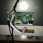
The two cables hanging down are the HDMI cable and the power supply. So now that I have the monitor situation secured, its time to add the brains of the operation, the Raspberry Pi.
I had already installed RetroPie to the Raspberry Pi. This involves downloading the RetroPie image (free) and installing it on the SIM card. (If you want further instruction you can ask me or find it online). Once that is done, all you have to do is to install your roms into the correct game folders. Each game system has its own folder. In my case, the initial setup was for arcade so that is where the roms were copied. Once that is accomplished, insert the SIM Card into the Raspberry Pi and you’re ready to plug in all the peripherals. For this cabinet that meant the power supply, the HDMI cable to the monitor, the control panel via USB cords, and the audio amp. All power supplies were plugged into a power wand.
This was the start with wand attached. The two secured wires are the USB cables from the control panel. Cable management is a matter of preference. It can be as neat or as sloppy as sense of decorum can handle. For a person as anal as I am, I am not a slave to extreme neatness as far as my wiring goes. That will explain why once I added the other pieces it started to look like a spider ‘s nest. I now have the amp, the speakers, and 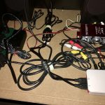
Raspberry Pi installed. Each were secured with the aforementioned double sided sticky tape. (The greatest invention since the post-it and white-out). You may also notice the amp is placed back where if I wanted to adjust the knobs I couldn’t when the back is on. I did that because the program itself has a volume control so I just set the amp at a reasonable volume and if I want to reduce it, I can do it from RetroPie. I also numbered the USB cables and the Raspberry Pi. The reason for that is to make sure that the player one controls are recognized as player one and not switched. That pretty much completes the inside. All that’s left is the new control panel.
Remember 20 years ago, or at the beginning of this article (same thing) when I said I would use the original CP as a template? Well that’s what I did, 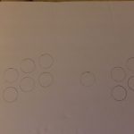
using a piece of foam board to trace the actual size and the button and joystick placement. Once I had the size down, I cut the panel out of a piece of 3/8 inch Luan (we call it plywood). Normally for a standard arcade cabinet, you would use 3/4” MDF (medium density fiberboard). In this case, that would be too thick. The original board is only 3/8 inch thick as is the rest of the material used in the cabinet. This was to cut down expense and weight.
So the board was cut and I used a 1 1/8” Forsner Bit with my drill press to cut the holes. You can also use a regular drill and a 1 1/8” spade bit. Once the holes are drilled, test fit your buttons to make sure they fit as they should. When you are satisfied, you need to make the panel more presentable. As always, you have options. You can sand the board smooth (as you should no matter what you decide on) and paint it. You can also go the route I did which was to purchase an adhesive vinyl covering. Admittedly, this does add another expense. It costs me about $19.00 (although with shipping it came to $31.82 for a 24’ roll). Shop around, but I highly recommend this if you’re like me and suck at painting.
So now that I had a covered panel, it is time to place the buttons and the joysticks. Fortunately, the button and joystick kit I purchased came with everything you would need as far as wiring, and USB interface boards. The kit comes with a wiring instruction page so you just follow the instructions. Two things to keep in mind. One, what ever order you wire your buttons, make sure that both players buttons are wired in the same order. In other words, Button one for Player One is wired exactly the same as Button One for Player Two. This will eliminate the possibility of controls for players getting mixed up. The other thing is important if you bought the light up buttons. The switch itself has no polarity issues. In other words, it doesn’t matter how you wire the switch, it will work either way. But the light requires a specific wiring order. Good test…if the light is not on, it needs for the wires to be switched.
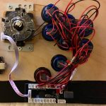
Remember when I said I was not a slave wiring neatness? Well this kind of proves it. Yikes! Believe it not, this monstrosity still worked, which is all that is important. So it was all wired up, all the buttons lit up, yay me! So I then put the panel down into place and CLUNK! I had placed the USB boards to close to the edge and it blocked it from setting all the way down. Figures! No problem. A quick relocation and it settled in nicely. Four screws later and a power up and boom! My son had a cabinet with a large selection of games he could play. There were a few adjustments to be made, but with a little patience, it works and I can hear my son tap, tapping away on the buttons on occasion. I call that a SUCCESS!
If you should ever decide to attempt this, I recommend it. Either by updating a previous  cabinet or by creating your own. I, in fact, also have almost completed a Bartop Cab with more light up goodness, including the Joysticks. It is very Shiny. If you SHOULD decide to go for it and you run into issues, I would be happy to help. Just leave a message and I’ll get back to you and remember that for all things Geek, look no further than GVNation.

Senior Writer at GeekVibesNation – I am a 60 something child of the 70’s who admits to being a Star Trek/Star Wars/Comic Book junkie who once dove headfirst over a cliff (Ok, it was a small hill) to try to rescue his Fantastic Four comic from a watery grave. I am married to a lovely woman who is as crazy as I am and the proud parent of a 21-year-old young man with autism. My wife and son are my real heroes.


